|

1551 Gene Autry Way, . Anaheim, CA 92805
Phone: 714.978.1551 . . . Fax: 714.978.0431
Specifications: Model 1700E Series, Automatic, Area-Slice Ball Bonders Last revised: 2/8/2000
Overview
This model series combines overhead ways and bond tools with the full 2400B Series software to locate and bond automatically a succession of line arrays on work pieces indexed along by customer’s conveyor. Bonding method can be either Single-Ball – "Ball in the Corner" – or Tab Bonding.

Application
The Single-Ball method connects two traces, presented as a vee, by placing and then severing a ball from the end of a stock of fine gold wire. The Tab method makes connections, without wire, by ultrasonically bonding a metal tab from one trace to the metallization of a second trace. Typically for either method, there are several traces per device and several devices held front-to-back in carriers moved along by conveyor.
This machine follows a programmed path through a long range in "Y" direction, and a short range in "X", and automatically makes all the bonds of all the devices of each carrier in turn. It locates each target by Pattern Recognition and corrects for placement error. The machine is narrow in configuration and contains all mechanism overhead, providing greatest convenience in joining to work conveyors.
Programming of the work path makes use of the fully developed and richly featured software from West Bond’s Model 2400B running under Windows 98. Interface is by keypad, mouse, and large color display.
Mechanical 
Bonding mechanism is constructed of three axes, straight-line and orthogonal, all driven by stepper motors in micro-step mode under program control. The long "Y" axis is moved via lead screw, and "X" and "Z", by linear spiral cams. A fourth motor drives the wire clamp assembly to sever wire and position it for ball formation by an air driven electronic torch wand. No motors are moved in "Z" direction to minimize inertia impact upon the bond. The vertical view video camera is moved on the "Y" axis at a measured offset to "X", and has sufficient field of view to scan the array of targets on that axis. In operation, coordinates of a next device are read while the previous device is being bonded. A microscope can be moved to view a large percentage of the bond range for setup verification.
Ranges, Ratios and Resolutions
|
Long "Y" |
Range |
6.000 inches |
|
|
Resolution |
0.00003125 inch per micro-step |
|
Short "X" |
Range |
0.500 inch |
|
|
Resolution |
0.00010229 inch per micro-step |
|
Bond "Z" |
Range |
0.500 inch |
|
|
Resolution |
0.00010229 inch per micro-step |
Bond Tool Head Assemblies 
The tool assembly is mounted on a four-bar linkage so the tool remains vertical and can be extended down to any position that tunes ultrasonically. In standard arrangement, the extended tool provides clearance of 0.28125 in. under the ultrasonic transducer stack, and 0.3750 in. everywhere else above the work plane. The standard set of force springs generates 10 to 250 grams, and together with the work-sensing firing switch, is built into the four-bar linkage. A dual force mechanism, operated pneumatically, acts to change between two pre-set force values, and either high or low force may be programmed for any bond.
Tool heads of this series are built around K~Sine Transducer, Model No. 24-W, one half wave in length, operating at a nominal frequency of 63 kHz. Actuation of all clamp motion is by the spiral cam of an inboard motor and is transferred through a linkage and ball bearing follower.
Electrical isolation is preserved between the clamps and the bond tool for ball formation by electronic torch.
Machine Configuration
The mechanism of this series was designed to mount above a customer's work handling system, to be confined entirely above the work plane, and so not to have any base or work platform. Mounting arms that descend to the table surface can be configured as required to join to customer’s mechanism.
Electrical Software and Hardware
A software control program, well developed and in long use for West Bond Model No. 2400B, is adapted to serve this model as well. This program runs under Windows 98. A Pentium III processor housed in an Industrial CPU enclosure executes the program. Pattern Recognition is accomplished by Matrox components. The User Interface is displayed on a large color monitor and consists of many screen forms that also include a display of the work piece targets. Input controls require only a keypad and mouse. User data of devices and of target image patterns can be stored and retrieved via floppy discs.
A separate enclosure holds electrical power supplies and also K~Sine Part No 6795, four Watts, dual channel ultrasonic power supply. Settings of power and time program values are sent via an eight-bit interface.
Definitions of Models of this Series:
- Model No. 1700E. This machine with tool assembly No.6920 for Ball Bonding.
- Model No. 1708E. This machine with tool assembly No.6920 for Ball Bonding. ESD Protected
- Model No. 1750E. This machine with tool assembly No. 6748 for Tab Bonding.
Note: This Model Series was originally designated 3500E instead of 1700E
Features available for "E" Models of this Series:
- Protective coating to protect against Electrostatic Discharge.
- Shielding method (Patent applied for) to prevent spark radiated damage.
Services
Compressed air, regulated to 50 psig, is required. Connection is via 1/4-inch tubing.
Electrical service required is 50-60 Hz, single phase, either 115 VAC or 230 VAC; however, input must be configured at the factory for 230 VAC. A fuse and three-prong power cord connector are provided for 115 VAC: For 230 VAC, these must be changed to conform to local requirements.
Dimensions
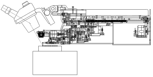
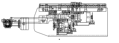
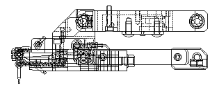
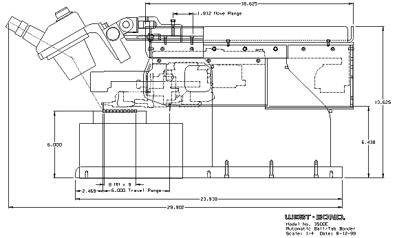
Machine size, exclusive of microscope and television monitor, is 11.813" wide x 23.938" deep x 13.625" high. Additional dimensions are shown on the drawings below. Weight is 75 lb. uncrated, or 110 lb. crated.
Side view:

|